

Contact Us
Tel:0755-27521059
Ms. Zeng:18027515661
Ms. Li:18928270202
Ms.Zhou:13590388442
Address:Guanlan High-tech Industrial Park,Longhua New District,Shenzhen 1st Floor,Building 2,Jiaquan Technology Building
E-mail:ctc@sz-ctc.com.cn

One of the self-cultivation articles for safety engineers | Determination of electrical clearance and creepage distance (new national standard GB4943.1-2022)
2022-09-07
Three hundred and sixty lines, each line out of the top, and in the safety inspection community of electronic products to establish a firm foothold, will do product structure inspection is the core, the core of the structural inspection is the determination of creepage distance and electrical clearance.
Professional explanation by CTC senior safety engineer: how to determine the electrical clearance and creepage distance?
(1) Transient voltages that may enter the equipment;
(2) The peak operating voltage generated in the equipment;
(3) Transient overvoltage;
(4) The frequency generated in the equipment. The peak operating voltage and the generated frequency in the equipment can usually be measured, and this paper mainly introduces how to determine the transient overvoltage and transient overvoltage.
Transient overvoltages are explained in standard IEC 60364-4-44 and generally refer to induced lightning in the atmosphere. According to the induction path, transient overvoltage can be divided into transient overvoltage in AC power grid, transient overvoltage in DC power grid and external circuit transient voltage.
(1) Transient overvoltage in AC grid
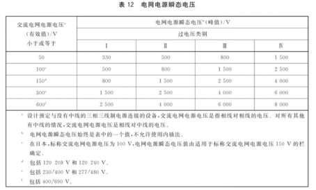
For equipment powered by AC mains, the grid supply transient voltage depends on the overvoltage category and the AC mains supply voltage, which can be determined according to the standard table 12. The electrical clearance of equipment normally intended to be connected to the AC mains supply shall be designed for Class II overvoltages. For example: 220VAC OVCII, transient overvoltage 2500V.
(2) Transient overvoltage in DC grid
a) If the grounded DC power supply system is completely in the same building, the single-point grounding transient overvoltage shall be 500V, and the grounding transient overvoltage on the distribution side and the equipment side shall be 350V respectively.
B) If the power distribution system is not grounded or is not in the same building, the transient voltage to ground shall be assumed to be equal to the transient voltage of the grid supply supplying the DC power source. For-48Vdc/60Vdc equipment in telecommunication centers, the grounding is usually in the same building and is a single point grounding, so the transient overvoltage is 500V, while the standard IEC 60950- 1 considers the transient overvoltage to be 71V in this case.
(3) External circuit transient voltage double conductor (shielded or unshielded) transient voltage is 1500V(10/700us).
► 1.2 transient overvoltage
For circuits directly connected to the AC mains supply, transient overvoltages are determined as follows:
(1) If the nominal grid power system voltage does not exceed 250V, the transient overvoltage value is considered to be 2000V peak;
(2) If the nominal grid power system voltage exceeds 250V but does not exceed 600V, the transient voltage value is considered to be 2500V peak.
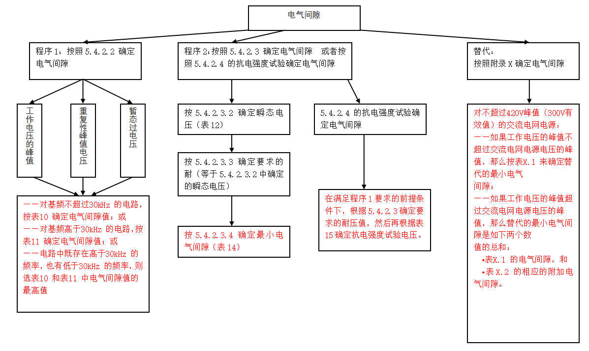
For the determination of the electrical clearance, the highest of the following two procedures shall be used:
(1) Procedure 1
The peak operating voltage is used to determine the electrical clearance; the peak operating voltage is the highest of the following voltages, depending on the use:
a) Steady-state voltage;
B) Repetitive peak voltage, which is considered to be 1.1 times of the grid power supply voltage;
c) Transient overvoltage;
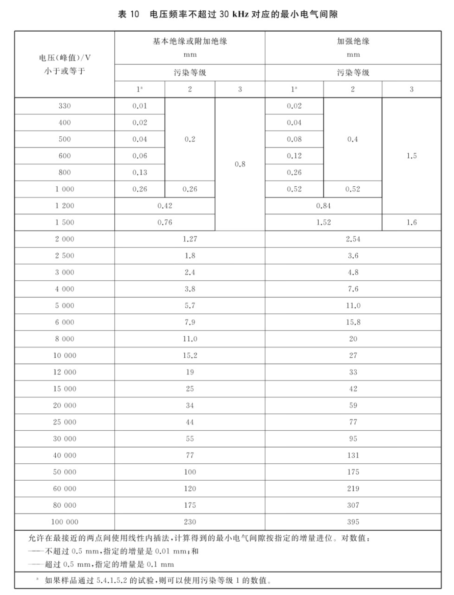
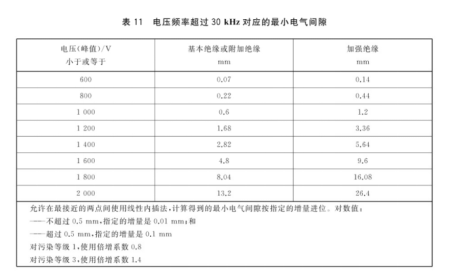
For circuits whose fundamental frequency does not exceed 30kHz, determine the electrical clearance value according to Table 10 of the standard; for circuits whose fundamental frequency is higher than 30kHz, determine the electrical clearance value according to Table 11 of the standard; if there are both frequencies higher than 30kHz and frequencies lower than 30kHz in the circuit, select the larger value in Table 10 and Table 11;
(2) Procedure 2
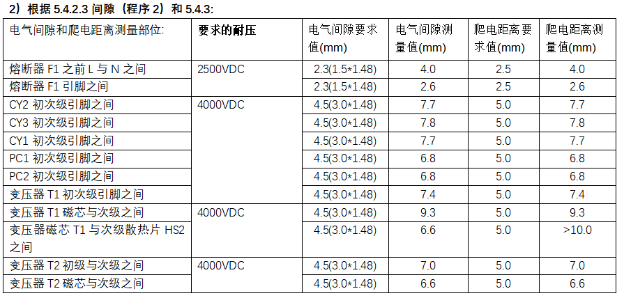
The electrical clearance is determined according to the withstand voltage required for use. Or by increasing the electrical strength test to determine the adequacy of the electrical gap, at this time should be maintained in accordance with the value determined in procedure 1; except for the 3 special cases listed in the standard, in general, the required withstand voltage should be equal to the transient overvoltage.
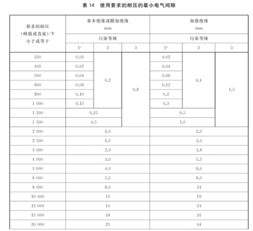
a) Determine the electrical clearance according to the withstand voltage required for use, in accordance with Table 14;
B) Use the electrical strength test to determine the adequacy of the electrical clearance, according to Table 15.
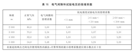
c) The electrical clearance and test voltage required above are applicable to altitudes below 2000m. For higher altitudes, the altitude multiplication factor shall be considered, which can be determined according to Standard Table 16.

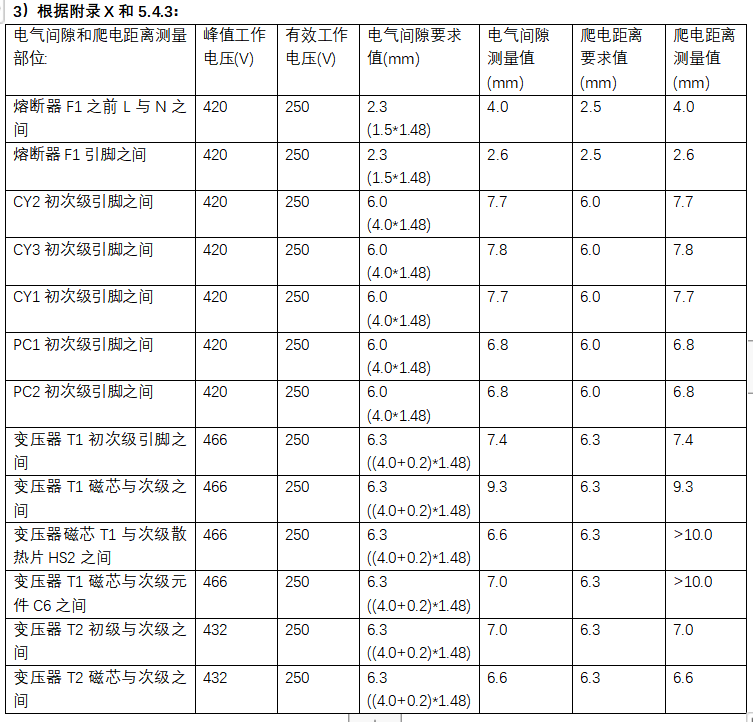
(3) Appendix X:
As an alternative, for overvoltage category II, the electrical clearance in the circuit connected to the AC mains supply not exceeding 420V peak (300V rms) can be determined according to Annex X.
For AC grid power supply not exceeding 420V peak (300V effective value):
-If the peak value of the operating voltage does not exceed the peak value of the AC grid supply voltage, then determine the alternative minimum electrical clearance according to Table X.1;
-If the peak value of the operating voltage exceeds the peak value of the AC mains supply voltage, the alternative minimum electrical clearance is the sum of the following two values:
• Electrical clearances in Table X.1, and
• Corresponding additional electrical clearances from Table X.2.
Table X.1 Alternative minimum electrical clearance for insulation in circuits connected to AC grid power supplies not exceeding 420V peak (300V effective value).
Table X.2 Additional electrical clearances for insulation in circuits connected to AC mains power not exceeding 420V peak (300V rms)

2. creepage distance
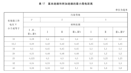
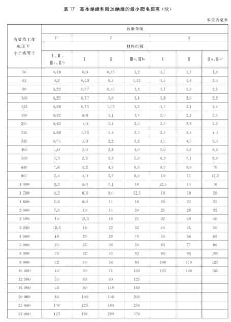
When the frequency is less than or equal to 30kHz, the creepage distance of basic insulation and additional insulation shall be determined according to Standard Table 17; when the frequency is more than 30kHz but less than or equal to 400kHz, the creepage distance of basic insulation and additional insulation shall be determined according to Standard Table 18.
For reinforced insulation, the creepage distance is twice the basic insulation requirement. When the reference table creepage distance value is less than the clearance value, the clearance value shall be used as the creepage distance value.
Pollution class 2 is generally applicable to all equipment included in the standard scope.
If the material group is unknown, it shall be assumed that the material group is IIIb.
When the equipment is connected to AC grid power supply, working voltage Vrms ≤ 250V, Vpeak ≤ 380V, working frequency 50/60Hz, overvoltage class OVCII, pollution class 2 and material group IIIb, the basic insulation and reinforced insulation electrical gap shall be determined according to the following procedures.
(1) Procedure 1: Determine the electrical clearance according to the peak operating voltage of the equipment
① Peak value of steady-state working voltage (380Vpk);② Repeated peak voltage (220*1.414*1.1=342.2Vpk);③ Transient voltage (2000Vpk), obtained from the maximum voltage in ① ② ③: 2000Vpk; According to the standard table 10, the electrical clearance is obtained: basic insulation 1.27mm, reinforced insulation 2.54mm.
(2) Procedure 2: Determine the electrical clearance according to the withstand voltage required by the equipment. Because the withstand voltage required by the equipment is equal to the transient voltage, and the transient voltage is determined by the standard Table 12, the required withstand voltage is 2500V(300 Vac,OVCII). According to the standard table 14, obtain the electric clearance: basic insulation 1.5mm, reinforced insulation 3.0mm.
Because Procedure 1
(3) Appendix X: According to Table X.1 in Appendix X, look-up table shows that Vpeak ≤ 380V is less than 420Vpeak, and electrical clearance is obtained: basic insulation 2.0mm, reinforced insulation 4.0mm.
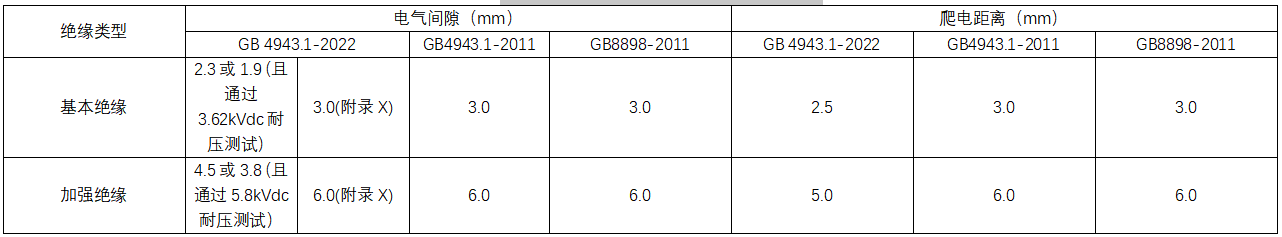
For the altitude of 5000m, according to the standard table 16, the electric clearance altitude multiplication coefficient is 1.48, and the voltage coefficient of resistance strength is 1.24. At this time, the minimum electrical clearance should be: basic insulation 1.5 × 1.48=2.3mm (Procedure 2), 2.0 × 1.48=3.0mm (Appendix X), reinforced insulation 3.0 × 1.48=4.5mm (Procedure 2), 4.0 × 1.48=6.0mm (Appendix X); or basic insulation 1.27 × 1.48=1.9mm and reinforced insulation 2.54 × 1.48=3.8mm, however, it must withstand the withstand voltage test with the basic insulation 2.92 × 1.24=3.62kVdc and the reinforced insulation 3.62 × 1.6=5.8kVdc (Procedure 1). Table 1 shows the comparison of the insulation distance requirements at an altitude of 2000m, and Table 2 shows the comparison of the insulation distance requirements at an altitude of 5000m.
Table 1 Difference Comparison of Insulation Distance Requirements at 2000m Altitude
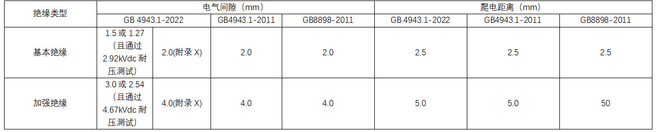
Table 2 Difference Comparison of Insulation Distance Requirements at 5000m Altitude
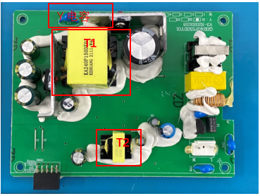
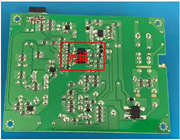
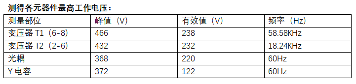
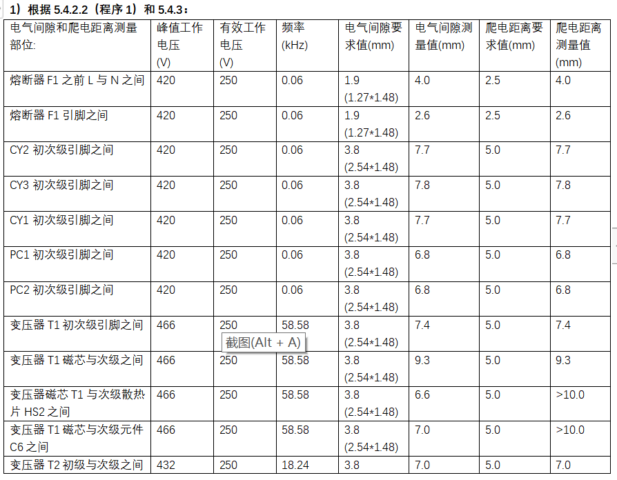
3. case analysis: the power board meets the altitude of 5000m.
Related News
Address:Guanlan High-tech Industrial Park, Longhua New District, Shenzhen 1st Floor, Building 2, Jiaquan Technology Building
Fax:(0086) 755 8611 6468

Focus on us


